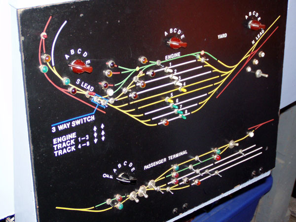
With the rotary switch block system, a main panel and various sub-panels is used to assign the blocks to one of five throttles. Here is the yard and passenger terminal panel. There is one rotary for the passenger area, and three for Yard Center. There are also various kill switches for certain tracks, and in the yard there are L-R SPDT switches that select between two leads. This was needed to allow trains to switch from both ends, but was always a hassle to remember to throw the toggle for the correct side.No worries with DCC, though. Just leave them in one of the "on" positions and you can work from either end! |
 |
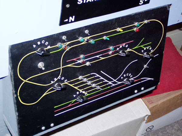
Another sub-panel is the one for the "Central Electric Division", or what used to be the Central Electric traction line. This trackage was split up into about six blocks, also with kill switches on some tracks and others that chose sides to get power from. The yard is not really there anymore as the diagram indicates. The main panel, which is not shown here, is very similar. Rotary switches for block power and toggles for power switches are the mainstay on that panel. |
 |
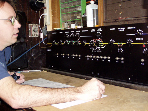 |
In 2005-2006, Bob Gallippi and Doug Butzow (shown here) worked to build and install a CTC-like panel on the work table, which allows a dispatcher to sit down at a desk and be slightly disconnected from the railroad as most real dispatchers are. By using the "off" position on the main panel's rotary switches, another group of rotaries could be placed on this panel to assign block power. This also provided a rudimentary method of keeping track of which trains has been assigned which blocks. Turnouts are controlled with another set of pole-changing toggle switches. This panel is still used with DCC, but only for turnout control. We hope to replace the rotary switches with block indication lights in the future. |
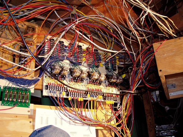 |
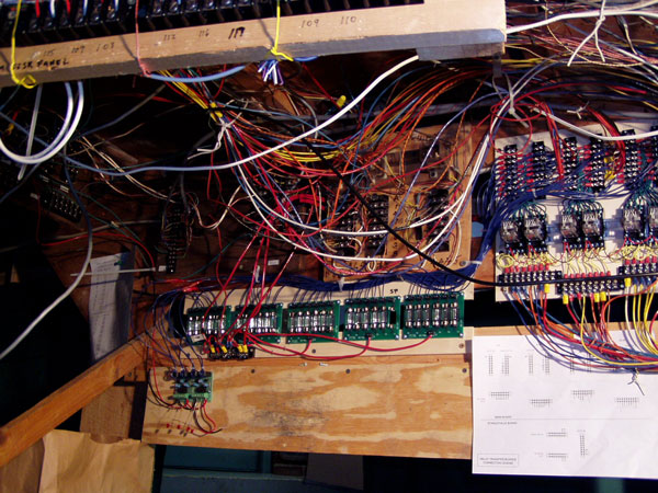
The first step to make the layout capable of being operated with either conventional analog throttles or DCC was to build and install a relay transfer system. By cutting into the trunk lines coming from the main panel, we removed the rotary switches from the equation when operating on DCC. Using 4PDT relays, all 29 blocks on the main part of the layout can be transferred with eight relays. Click here to see a PDF of the diagram for the basic switching concept that transfers block power from the rotary switches to the DCC boosters. |
Also installed next to the relay board were this group of "ballast lamp" block protectors, as shown on the diagram referenced above. Cheaper than DCC circuit breakers, they cushion each booster from direct shorts and will light up brightly to indicate which block is shorted. Called the CP6 module from NCE, they came with a lamp that was too small, wattage-wise (14W) and would glow whenever a heavier locomotive load was present. Switching to 21W lamps solved the problem. Also seen below the lamps are the test block detectors installed recently. Based on current-sense transformers, we hope to have all blocks detectable in the future. |
 |
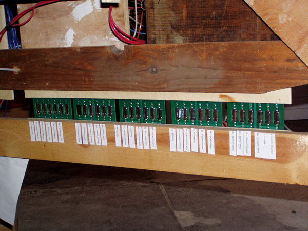
Here is what the main lamp board looks like from the other side, visible from the main aisle in the middle of the layout. Each lamp is labled for which block it protects, and operators can find out quickly which block has the short. The lamps are BRIGHT when fully illuminated. The large red wires that you see in the picture are the main bus lines from the three boosters that feed the lamp boards. One thing that DCC demands is heavy current-carrying capacity, especilly if you run a lot of sound locomotives. There is a bunch of 12-gauge employed for such bus lines and even some 10-gauge that goes across the aisle to the old traction section panel. That has its own relay transfer system but runs off the same booster that powers the yard. Always wire heavier than you need to with DCC! |
 |
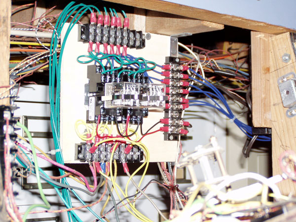 |
This is the interior of the Stanleyville "Central Electric Division" subpanel. As you can see, it has its own relay transfer system since the distance to carry wires back and forth from the rotary switches was too far compared to what we did on the other sub-panels on the same side of the aisle as the boosters and main relay board. The green wires are from the rotary switches and the blue wires come from the lamp board for this section. That board is fed by a #10 wire from the 3rd booster, which also feeds the yard and engine terminal on the "main" layout. |
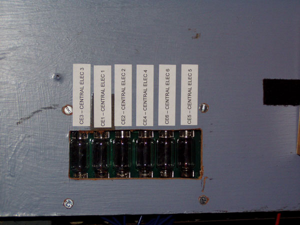 |
And this is the Central Electric Division's lamp board, similar to the main lamp board but only one unit (six lamps) and behind a Plexiglass window that Doug Butzow made. Again, labels indicate which block is shorted, but these numbers don't mean much since they aren't shown on the face of the panel. This section of railroad used to be powered by an overhead wire, so when it was converted to 2-rail operation the blocks weren't named like the mainline. |