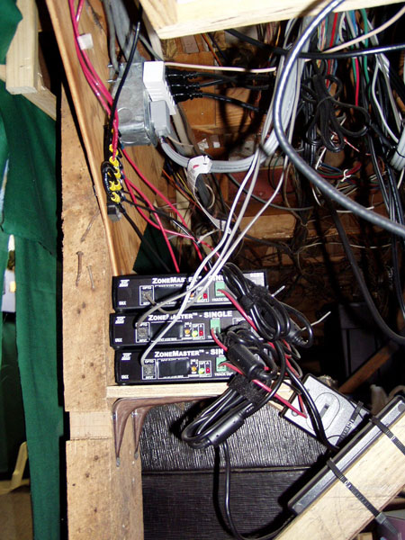
The boosters used on the Rossville layout are the newer ones produced by CVP Products, makers of the Easy DCC system. They call them ZoneMasters, and each is capable of 7 amps continuous with a 10 amp surge rate. This is good for sound locomotives which have large currents at start up to charge capacitors. Note those big 12-gauge red bus wires sneaking down from the top, and the "DCC master" outlet above the boosters that is controlled by one of the transfer relays. The key to any DCC system with multiple booster is to only have ONE common in the system. This is usually the command bus, but since a common-rail system already has that one track connection as common, you must use boosters that have opto-isolated inputs as the ZoneMasters do. A simple telephone 3-way splitter is used after the command box to split the signal to the three inputs. Note there is tape over the normal command bus in/out ports to keep them from being used. You can also make out the DC switching power supplies for the boosters tie-wrapped to the diagonal cross braces. |
 |
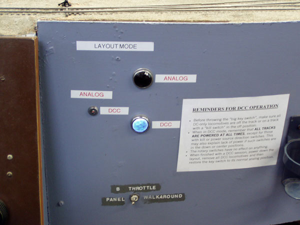
This shows the key switch that changes modes as well as the indicator lights. We decided that not just anyone, especially not visiting children, should be able to switch the mode to DCC. The brown slab to the left is the edge of the main panel, and you can see the corner of the knob for the "B" stationery analog throttle. The switch at the very bottom is for switching that cab between the stationery throttle and a walk-around. We had a couple of radio throttles and several cabled ones for portable use, but nothing beats DCC for flexibility.All throttles with it are radio, save for one cabled one that the yardmaster uses. |
 |
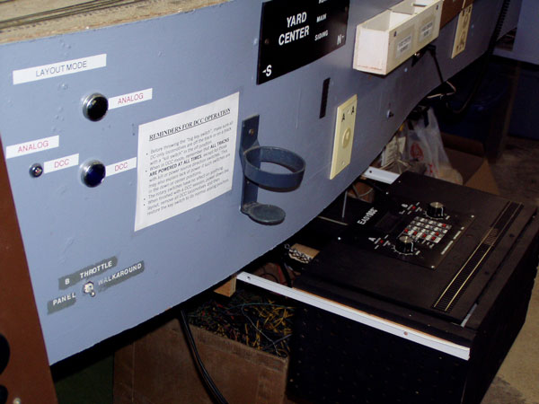 |
This is an overview of the mode switch area on the fascia and the slide-out box that houses the EasyDCC command station. The box was orignally built as a portable system, but once we saw how well it integrated with the layout it was decided to mount it more or less permanantly. You can just make out on the back of the box the small shelf that holds the radio receiver, of which you can see the small silver stick antenna sticking up. The EasyDCC command station is pretty unique. They supply it like they expect you to mount it in a cut-out somewhere on your fascia, or in a drawer. Ours is more the latter. |
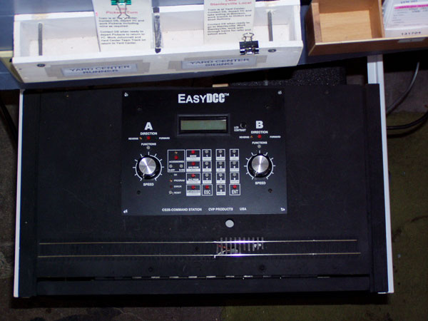 |
Looking down on the Command Station reveals all the buttons and the two fixed throttle knobs which few people ever use. We set up a programming track to use with the command station, but now a short strech of track near the computer allows us to use an SPROG and JMRI, which is a much easier way to program decoders as they get more complex with or without sound. You only need to access this panel when you are setting up consists or verifying throttle ID numbers. Otherwise, it stays slid under the layout during operations. |
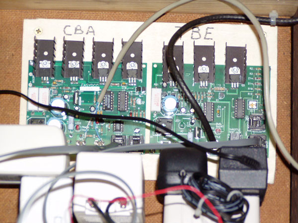
Inside the command station box, with the CS itself still in the "lid" that is flipped up and invisible here, are the Command Bus Amplifier (CBA) and the Throttle Bus Extender (TBE). The CBA is a modified Booster 3 that came with the original EasyDCC system from the Ebay Auction. It takes the signal from the command station and amplifies it, at a lower level than normal track voltages and currents, to drive the opto inputs on the boosters. The TBE uses coax cable to gather in throttle data from jacks around the layout and the radio receiver. Think 10Base2, or ThinNet Ethernet to understand this bus, which must be terminated with a 75 ohm load, in this case provided by the radio receiver. The blue-white telephone cable is the output to the boosters. |
 |
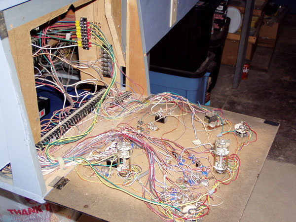
An example of the extra things we needed to do to make this a dual-mode system were the connections to the sub-panels. In this case, the yard panel is open and you can see extra wires with the bright yellow crimp terminals. We had standardized on wire colors like this: Blue=DCC from boosters, Green=Analog from rotary switches and Yellow=Dual mode to blocks. But on these panels, we had to take the analog signal from the rotaries back to the relay board, and bring dual-mode wires back to cut-off switches that were wired directly to the rotaries before. The problem wasn't easy to understand, so we made a diagram that might help the outsider understand it better. Bottom line, don't use common rail on an old system if you don't have to! |
 |